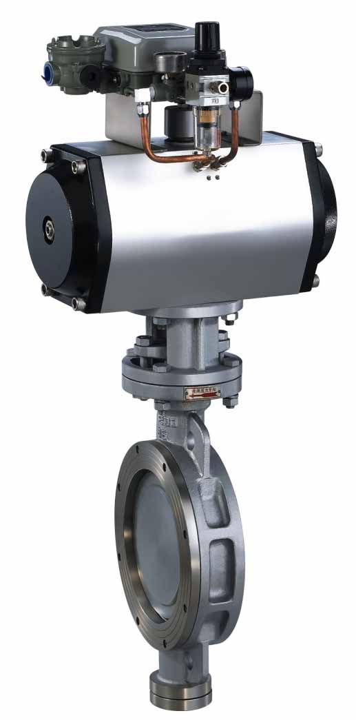
气动对夹式硬密封蝶阀
PNEUMATIC WAFER TYPE HARD-SEALED BUTTERFLY VALVE
JLD673H(C、P、R)-PN10、16、25,CLASS150、300
技术规范 Technical specification
|
设计依据
Design reference |
GB标准 |
|
设计标准
Design standard |
GB/12237 |
|
结构长度
Face To face |
对夹式连接
Wafer Type connecting |
GB/12221 |
|
法兰尺寸
Wafer Flange Size |
GB/9113、JB/T79 |
|
试验和检验
Test&inspection |
JB/T9002 |
※注:系列蝶阀结构长度及连接对夹法兰尺寸可根据用户要求设计制造
Note:The struturalength and connercting flange size of ball valve
Series can be designed and manufactured as per users requirements
主要零件材质表 Form of Major Parts Materials
|
序号
No |
零件名称
Accessory name |
材质 |
|
C |
P |
R |
|
1 |
内六螺丝
Mild steel Hex socket screw |
1Cr18Ni9Ti |
1Cr18Ni9Ti |
1Cr18Ni12Mo2Ti |
|
2 |
阀盖Cover |
WCB |
1Cr18Ni9Ti |
ZG1Cr18Ni12Mo2Ti |
|
3 |
垫片Gasket |
不锈钢+柔性石墨
Stainless Steel+Graphite |
不锈钢+柔性石墨
Stainless Steel+Graphite |
不锈钢+柔性石墨
Stainless Steel+Graphite |
|
4 |
阀座Seat |
1Cr18Ni9Ti |
1Cr18Ni9Ti |
1Cr18Ni12Mo2Ti |
|
5 |
垫片 Gasket |
不锈钢+柔性石墨
Stainless Steel+Graphite |
不锈钢+柔性石墨
Stainless Steel+Graphite |
不锈钢+柔性石墨
Stainless Steel+Graphite |
|
6 |
蝶板Butterfly plate |
WCB |
ZG1Cr18Ni12Mo2Ti |
ZG1Cr18Ni12Mo2Ti |
|
7 |
圆柱销Straight Pin |
45 |
1Cr18Ni9Ti |
1Cr18Ni12Mo2Ti |
|
8 |
下盖Bottom Cover |
WCB |
ZG1Cr18Ni9Ti |
ZG1Cr18Ni12Mo2Ti |
|
9 |
垫片Gasket |
不锈钢+柔性石墨
Stainless Steel+Graphite |
不锈钢+柔性石墨
Stainless Steel+Graphite |
不锈钢+柔性石墨
Stainless Steel+Graphite |
|
10 |
衬套Bushing |
PTFF+不锈钢
PTFF+Stainless Steel |
PTFF+不锈钢
PTFF+Stainless Steel |
PTFF+不锈钢
PTFF+Stainless Steel |
|
11 |
阀体Body |
WCB |
ZG1Cr18Ni9Ti |
ZG1Cr18Ni12Mo2Ti |
|
12 |
阀杆Stem |
1Cr13 |
1Cr18Ni9Ti |
1Cr18Ni12Mo2Ti |
|
13 |
连接支架Connecting Yoke |
WCB |
WCB |
WCB |
|
14 |
键Key |
45 |
45 |
45 |
|
15 |
衬套Bushing |
PTFF+不锈钢 |
PTFF+不锈钢 |
PTFF+不锈钢 |
|
16 |
填料Packing |
柔性石墨 Graphite |
柔性石墨 Graphite |
柔性石墨 Graphite |
|
17 |
压盖Gland |
WCB |
ZG1Cr18Ni9Ti |
ZG1Cr18Ni12Mo2Ti |
|
18 |
气动装置
Pneumatic Device |
|
|
|
|
19 |
位置指示器
Location Indicator |
塑料Plastic |
塑料Plastic |
塑料Plastic |
*注:主要零部件及密封圈的材质亦可根据实际工况条件或用户特殊要求设计选用.
Note:The main spare parts and sealing-ring materals of ball valve series can be designed for options as per real
working conditions and users special reauirements.

主要外形及连接尺寸 JLD673H Mani Outline and Connecting Flange Size
|
公称通径DN |
外形尺寸 Outline Size |
|
L |
H |
D1(1.0) |
D1(1.6) |
D1(2.5) |
n-Φd(1.0) |
n-Φd(1.6) |
n-Φd(2.5) |
|
50 |
43 |
112 |
125 |
125 |
125 |
4-14 |
4-14 |
4-18 |
|
65 |
46 |
115 |
145 |
145 |
145 |
4-14 |
4-14 |
8-18 |
|
80 |
49 |
120 |
160 |
160 |
160 |
4-18 |
8-18 |
8-18 |
|
100 |
56 |
138 |
180 |
180 |
190 |
4-18 |
8-18 |
8-22 |
|
125 |
64 |
165 |
210 |
210 |
220 |
8-18 |
8-18 |
8-26 |
|
150 |
70 |
175 |
240 |
240 |
250 |
8-18 |
8-22 |
8-26 |
|
200 |
71 |
208 |
295 |
295 |
310 |
8-18 |
12-22 |
12-26 |
|
250 |
76 |
243 |
350 |
355 |
370 |
12-18 |
12-26 |
12-30 |
|
300 |
83 |
283 |
400 |
410 |
430 |
12-22 |
12-26 |
16-30 |
|
350 |
92 |
310 |
460 |
470 |
490 |
12-22 |
16-22 |
16-33 |
|
400 |
102 |
340 |
515 |
525 |
550 |
16-22 |
12-30 |
16-36 |
|
450 |
114 |
380 |
565 |
585 |
600 |
16-22 |
20-30 |
20-36 |
|
500 |
127 |
410 |
620 |
650 |
660 |
20-22 |
20-33 |
20-36 |
|
600 |
154 |
470 |
725 |
770 |
770 |
20-26 |
20-36 |
20-39 |
|
700 |
165 |
550 |
840 |
840 |
875 |
24-26 |
24-36 |
24-42 |
|
800 |
190 |
640 |
950 |
950 |
990 |
24-30 |
24-39 |
24-48 |
|
900 |
203 |
710 |
1050 |
1050 |
1090 |
24-30 |
28-39 |
28-48 |
|
1000 |
216 |
770 |
1160 |
1170 |
1210 |
28-30 |
28-42 |
28-56 |
|
1200 |
254 |
890 |
1380 |
1390 |
1420 |
32-33 |
32-48 |
32-56 |